Down at the club shack last Friday night, I was attempting to listen to John Berry's excellent talk on Sporadic E whilst also trying to permanently install the KiwiSDR. I shamefully have to admit that I didn't get to hear enough of the talk for it to make much sense to me, but thankfully John has reconstituted enough material to generate a superb reference presentation for us on YouTube - but more on that elsewhere.
So the KiwiSDR is now up and running in its forever home, and the better quality Wellbrook antenna combined with the additional 25m of elevation relative to my QTH have given it a useful boost in performance. I'm not going to linger on that here either, because I also got the chance to run my NanoVNA up against the new end-fed HF antenna - something I had to do because the suspense was just killing me!
This article then will briefly cover the results of that analysis. I'm not an expert on VNAs, but I use mine for everything antenna-related to the point that my expensive MFJ-259C rarely sees the light of day - at least for SWR measurements.
Having an instant graphical visualisation across a wide frequency range tells a far more powerful story than a few random spot-checks on individual frequencies. You might well reflect on the fact that I'm saying that analogue representations are often far more useful that digital ones. Never let it be said that I'm an analogue-basher.
I re-calibrated my Nano just before setting out on Friday, just to make sure. It has to be borne in mind that conditions were 'moist' out there in Burgess Hill, so that will have an effect (one that, and correct me if I'm wrong, will tend to slightly lower SWR figures across the board) as well as somehow trying to reconcile that of the unusual material in the roof structure at Cyprus Hall, which is apparently particularly RF reactive in some way.
Still, let's take a look at the overall sweep graph.
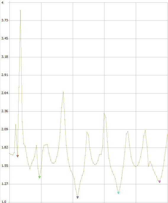
I was generally encouraged by that. At least it wasn't completely unrecognisable - but let's take a look at what this really shows us.
The five markers, which I've manually placed at the visible low-points of the SWR curve, relate to the five minimums that will probably be of most interest to us.
The SWR scale is displayed on the 'Y' axis, whilst the 'X' axis is obviously frequency, though it's not marked on here due to the reduced screen resolution of my laptop, and the fact that I was in a bit of a rush to grab something and save it. What I can tell you (and you will see this broken down in the other images below) is that the frequency range is from 1.8MHz on the left, all the way up to 30MHz on the right.
Those markers represent the resonant points on the bands for which the 80m - 10m EFHW is 'designed'. They are (loosely speaking) 80m, 40m, 20m, 15m and 10m.
Below you will be able to see the frequencies associated with those low points. A couple fall slightly outside of the amateur bands, but of course nearly any multi-band antenna is going to be a compromise, and we find that most are on the low side, but that 15m and 10m are pretty good. Overall they might be a bit low - indicating that the main element (between the transformer and the coil) is slightly too long, but let's see what it does in different conditions.
The one notable exception is 80m which is way too low, demonstrating that the 2.4m long extension beyond the coil is quite a bit too long and may need a few inches cut off or folded back. Again, let's see what dry weather and different ambient conditions bring.
What I have noticed with my version of this antenna is that despite the fact that everyone will tell you that you should get the main element tuned correctly fist, then add the coil and extension wire before additionally tuning that, and that the second step will not have any effect on the first, that this is in fact not true. At least that's my experience, and that's after a very painstaking, analytical and iterative tuning programme. That's not to say that you should abandon that approach - it's still fundamentally the correct sequence - but always leave the main element a bit longer than initially indicated, because you're likely to need that wiggle room later.

Here you can see the sweep criteria, and the relative positions of the markers. This is just where I happened to place them as a best guess based on the graph. You might be able to see that the colours of the markers tie up with those on the image above.
This is where you set the sweep range (1.8MHz to 30MHz in this case). Note that you have to have previously calibrated for this range and saved the configuration prior to starting the sweep. You can also set the 'Segments' parameter here, which is basically the 'resolution' of the sampling. I'm going to stick my neck out and directly liken it to the 'Sampling Rate'. More samples, more accuracy. Taking too many samples in wasteful and unnecessary, but taking too few samples can give rise to some strange and unrepresentative results, as you may appreciate if you know a little of the theory of DSP, ADC and of the Nyquist-Shannon sampling theorem. In the case of our end-fed though, we know where we expect to find the dips, and thankfully science hasn't let us down.
Lastly we can see the actual (sampled) minimums of SWR and the frequencies at which they occur, as well as the associated impedances, inductance and capacitance figures and the return losses. Some of this is interesting to me, some of it is lost to the mists of time and/or to the deterioration of my neural pathways since taking my exams.

In summary, it looks pretty good to me. I'll re-run the test in dry conditions soon and see what we get, but in the meantime Peter G4AKG has scribbled down some ATU tuning presets that anyone operating HF into this antenna can draw on. They exclude the WARC bands at present, but we'll add those soon, before Stella has a couple of nice laminated versions made up.
If we can drop the coil end and abbreviate the 80m extension a tad, then I guess we'll try to do that before the weather gets much colder and wetter. We should be able to achieve that without getting all caught up in the chickenwire mesh that runs rather unhelpfully along the gutter line of the hall roof.
So there you go. I hope you found that useful or interesting. I understand that the hope is that we will now be able to put some more miles on the HF kit that lives in the darkness of the shack, and I hope that transpires. It will only be of any use to me when we have a radio on the end of this antenna that we can access from somewhere that you can see your hand in front of your face and at a time that's convenient. Having the shack is great, but it's no longer necessary to concertina yourself into a space that uncomfortable and unpleasant just to get on the air!
And while I'm at it, I noticed that the cooling fan in the Yaesu FT-847 sounds like a gas turbine-powered threshing machine in a gravel pit. Is there anybody in the club that's willing to take the lid off that thing and fit a new one? It's properly deafening!
Best 73's
Berni M0XYF :p